Another word I’ve heard buzzing around lately, microservices works to brings cloud and containers a step further and modularizes the application into smaller function-specific mini applications that work together through APIs. With this approach, the elasticity of the cloud is tuned to the needs of the subscribers, and the business only pays for the network and compute resources they need on a more granular level. The early adopters at this point are the usual suspects: Airbnb, Uber and Netflix.

“the microservice architectural style is an approach to developing a single application as a suite of small services, each running in its own process and communicating with lightweight mechanisms, often an HTTP resource API.”

Principals of Microservices (PPT)

Cisco’s APIC-EM, or Application Policy Infrastructure Controller Enterprise Module is an OpenDayLight based SDN (Software Defined Network) controller. You could also possibly call it Cisco’s attempt to Merakify the Enterprise. On the bright side, it’s a free virtual appliance and no license is required.

One of the biggest features of APIC-EM is called Network Plug and Play

At a high level, the Cisco switch or router talks to the APIC-EM to streamline workflows and automate deployments. Switches and routers, known as agents discover the controller using any of the following mechanisms in order:

dhcp option 43 or dns (below), usb key, cloud discovery (currently beta), or the smartphone app.

DHCP

option 43 ascii "5A1N;B2;K4;I172.19.45.222;J80"

The option 43 string has the following components, delimited by semicolons:

  • 5A1N;—Specifies the DHCP suboption for Plug and Play, active operation, version 1, no debug information. It is not necessary to change this part of the string.
  • B2;—IP address type:
    • B1 = hostname
    • B2 = IPv4 (default)
  • Ixxx.xxx.xxx.xxx ;—IP address or hostname of the APIC-EM controller (following a capital letter i). In this example, the IP address is 172.19.45.222.
  • Jxxxx —Port number to use to connect to the APIC-EM controller. In this example, the port number is 80. The default is port 80 for HTTP and port 443 for HTTPS.
  • K4;—Transport protocol to be used between the Cisco Plug and Play IOS Agent and the server:
    • K4 = HTTP (default)
    • K5 = HTTPS

DNS

APIC-EM: pnpserver.<customerdomain>.com
NTP Server: pnpntpserver.<customerdomain>.com

The DHCP pool will need to either be on vlan 1, or you’ll need to specify a staging vlan on the upstream switch:

pnp startup-vlan 55

That brings me to another caveat of of Plug and Play is that the firmware needs to be supported, and may not match the shipping version of the hardware!

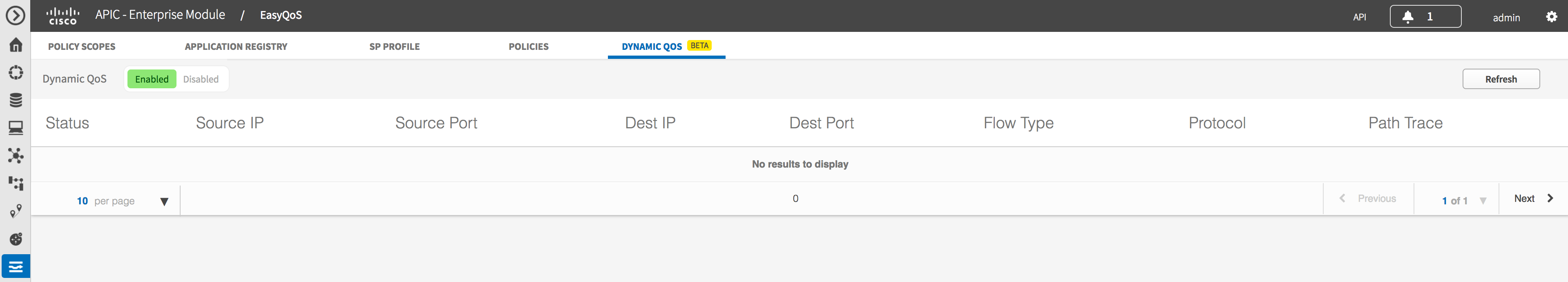
Another feature of APIC-EM is called Easy QoS

I actually really like this use-case for network programmability. It’s important for the policies to match end-to-end in QoS, so being able to roll out policies and get insights into your policy-maps holistically is kind of a big deal.

APIC-EM documentation gives the concept of Northbound, which is the REST API you can use for custom applications, and Southbound in which APIC-EM talks to hardware using SNMP and CLI. Cisco states “future APIC-EM releases will leverage other southbound technology such as NetConf as they become available”.

I found some Postman collections from CiscoDevNet’s Github page here. Postman collections are a great way to learn by doing.

APIC-EM Firmware Compatibility

Official Getting Started Guide

As a person who enjoys weekends and sleep, my favorite friday night cutover is one that lasts approximately 30 seconds. To do this, you need three things:

-Enough resources to temporarily have two of everything
-A portgroup configured with an isolated VLAN
-A staging PC for use as an NTP server (I recommend Meinberg NTP for that)

After building and testing your new environment, you’ll want to “flip the nics” to make the new system live:

Connect-viserver vcenter01.dom.com -User admin -Password pass

Get-Cluster “Old-UC-Cluster” | Get-VM | Get-NetworkAdapter | set-networkadapter -Connected:$false -Confirm:$false

Get-Cluster “New-UC-Cluster” | Get-VM | Get-NetworkAdapter | Set-NetworkAdapter -Portgroup “VLAN 9” -Confirm:$false

This is in a sunny day scenario where everything in the whole cluster is disconnected while everything in another is connected. Sometimes you need to apply some logic to exclude some vms that happen to coexist within the same cluster:

Get-Cluster “New-UC-Cluster” | Get-VM | Get-NetworkAdapter | Where {$_.NetworkName -eq “VLAN 3” -and $_.Name -notlike “CUCMSUB2”} | Set-NetworkAdapter -Portgroup “VLAN 9” -Confirm:$false

UC applications aren’t only supported by Cisco on a virtual platform now, it’s the ONLY supported platform. As a “Collaboration Engineer” by title, I am usually focused on only a handful of applications, traditionally relying on the “Datacenter Guy” to provide the infrastructure and hope it works. But, it’s always good to see the whole picture.

In my opinion, virtualization is something everyone needs to know at least the basics of. You might not be the one adding a vlan to a switch anymore, but you still need to know networking.

Each VM contains two basic files: one .vmx (configuration) and one .vmdk (disc)
The .vmdk (disc) is considerably larger and contains all the bits a physical hard drive would. The .vmx (configuration) is a small, editable file containing all of the settings a physical bios chip would.

A few items you’ll find in a .vmx file:
numvcpus = “2”
memsize = “6144”
scsi0:0.fileName = “UCCX1.vmdk”
ethernet0.networkName = “Voice_VLAN”
guestOS = “rhel4”
sched.cpu.min = “1300”
sched.cpu.units = “mhz”
sched.cpu.shares = “normal”
sched.mem.minsize = “6144”
sched.mem.shares = “normal”
One task any Cisco UC Engineer will go through at least once is an upgrade from pre 8.6 to post 8.6 version. Two changes come about: an OS change from Redhat 4/5 to 6, and adapter change from flexible to vmxnet3.

One method is to edit the .vmx by finding it on the datastore, downloading the file, making the edits below, and import it back:
guestOS = “rhel6_64guest”
ethernet0.virtualDev = “vmxnet3”
An easier method if you are doing multiple servers/clusters at once is to use PowerCLI
Connect-VIServer -Server vcenter01 -User admin -Password pass
Set-ExecutionPolicy RemoteSigned
Set-VM -VM ‘UCCX Pub’ -GuestId “rhel6_64guest” -Confirm:$false
Get-VM ‘UCCX Pub’ | get-networkadapter | set-networkadapter -type vmxnet3

Adding to my post from monday, I had another issue with SRM not changing ip addresses on an Asterisk (CentOS) box, so I had to engineer a workaround..

For PRIMARY = 10.100.1.150 and DR = 10.100.2.150

1. On the linux box, we’ll create two bash scripts, chmod these 755 and stick these in your $PATH.

primary-to-dr.sh
#!/bin/sh
ifconfig eth0 10.100.2.150 netmask 255.255.255.0 up
route add default gw 10.100.2.1 eth0
done

dr-to-primary.sh
#!/bin/sh
ifconfig eth0 10.100.1.150 netmask 255.255.255.0 up
route add default gw 10.100.1.1 eth0
done

2. On the vCenter, install WinSCP and run. Create 2 new sessions with saved credentials and name primary and dr. Connect to each session and accept the certificates!
3. Ensure the following is in the windows PATH, if not, add this directory: C:Program Files (x86)WinSCP
4. Create the batch file below to call winscp, start the session and run the relevant script from step 1.

ifconfig.bat
@echo off
echo “Logging into host and running script”
If EXIST c:primary.txt (winscp primary /command “call primary-to-dr.sh”) ELSE (winscp dr /command “call dr-to-primary.sh”)
echo Exit Value %ERRORLEVEL%
TIMEOUT /t 5 /nobreak

In SRM run the bat file, no flags needed.

VMware advertises the ability to “perform fully automated orchestration of site failover and fallback with a single click.” While this technology is extremely easy to setup and use, it’s oftentimes the small things that cause the biggest headache. SRM uses dns to propogate ip changes from the primary to secondary virtual machines. With windows this is automatic: the servers simply register their new ip addresses in dns. For linux servers, however this is not so easy, especially in my case (an avaya phone system) which provides no access to the CLI. The fix is to create a script.

DNS Server – 192.168.10.1
Primary Site Avaya – 192.168.10.35
Failover Site Avaya- 192.168.15.35

First you’ll want to make sure you are running the SRM service as an account with domain admin rights (assuming you setup the database with windows authentication during setup).

Next you’ll need DNSCMD from the RSAT (remote server administration tools), which you can find here

Below is an example script:

@echo OFF
echo “Removing Records from DNS…”
dnscmd 192.168.10.1 /recorddelete dom.local AVAYA-SRV-01 A /f
echo Exit Value:  %ERRORLEVEL%
TIMEOUT /t 3 /nobreak
dnscmd 192.168.10.1 /recorddelete dom.local AVAYA-SRV-01 A /f
echo Exit Value:  %ERRORLEVEL%
TIMEOUT /t 3 /nobreak

@echo off
echo “Adding Records to DNS ..”
If EXIST c:primary.txt (dnscmd 192.168.10.1 /recordadd dom.local AVAYA-SRV-01 A 192.168.10.35) ELSE (dnscmd 192.168.16.58 /recordadd dom.local AVAYA-SRV-01 A 192.168.15.35)
echo Exit Value:  %ERRORLEVEL%
TIMEOUT /t 5 /nobreak

In SRM, you’ll call the script as:
C:windowssystem32cmd.exe /c c:srmscriptsdnschange.bat

Also, you may notice the “If EXIST c:primary.txt”
It was the most elegant way I could think of the check if the system was in a failover state. This file will exist only on the primary side. Credit to Derek Bickel on this one!

Suppose we are a service provider carrying multiple tenants across our network. This is actually pretty simple and doesn’t require carrier-grade equipment.

In this example we’ll have an inner tag (customer) and an outer tag (provider). We’ll add 14 to the max mtu size on the provider switch to accommodate for the second tag.

The outer tag uses both the “switchport mode access” to define the customer and “switchport mode dot1q-tunnel” to tell that it’s twice encapsulated.

You can “hop off” the outer tag at the CPE depending on what vlan you assign them.

This is the basics of q-in-q. With this you can provide “metro-e” or “private clouds” really its just basic vlans inside of vlans!
8021qinq


So can you also do router-on-a-router-on-a-stick ? Sure can..

2921(config)# interface gigabitethernet 0/1/0
2921(config-if)# dot1q tunneling ethertype 0x9100
2921(config-if)# interface gigabitethernet 1/1/0.1
2921(config-subif)# encapsulation dot1q 100 second-dot1q 200

Read more about it : at cisco’s site

monitor session 1 type erspan-source
erspan-id 1
vrf default
destination ip 10.1.x.y
source vlan 1-2,4,6-7,10,12,14,16,18,20,22,28,30,33,40,50,60,100,122,199-200,202 both
source vlan 211-212,222,230,236,240,998-999 both
no shut

monitor erspan origin ip-address y.y.y.y global

destination ip is of course your L3 based sniffing tool…like ExtraHop
y.y.y.y in this example is a management IP on my default VRF.

It surprises me how many times people invest the money in having a redundant edge, but fail to do the simple things: plug into different power sources and have their switch be a single point of failure. With this configuration, you could lose a power source, a firewall, a switch in the stack, and 75% of your cables and still function!

Configure Switch Stack:

vlan 10
name LAN

vlan 777
name ISP1

interface Port-channel1
description Primary ASA
switchport trunk allowed vlan 10,777
switchport mode trunk
!
interface Port-channel2
description Secondary ASA
switchport trunk allowed vlan 10,777
switchport mode trunk
!
interface GigabitEthernet1/0/47
description Primary ASA
switchport trunk allowed vlan 10,777
switchport mode trunk
channel-group 1 mode active
!
interface GigabitEthernet1/0/48
description Secondary ASA
switchport trunk allowed vlan 10,777
switchport mode trunk
channel-group 2 mode active
!
interface GigabitEthernet2/0/47
description Primary ASA
switchport trunk allowed vlan 10,777
switchport mode trunk
channel-group 1 mode active
!
interface GigabitEthernet2/0/48
description Secondary ASA
switchport trunk allowed vlan 10,777
switchport mode trunk
channel-group 2 mode active
!

Configuration Primary ASA:

interface GigabitEthernet0/0
channel-group 1 mode active
no nameif
no security-level
no ip address
!
interface GigabitEthernet0/1
channel-group 1 mode active
no nameif
no security-level
no ip address
!
interface Port-channel1
no nameif
no security-level
no ip address
!
interface Port-channel1.10
vlan 10
nameif LAN
security-level 100
ip address 172.17.10.10 255.255.255.0 standby 172.17.10.11
!
interface Port-channel1.777
vlan 777
nameif ISP1
security-level 0
ip address 24.222.111.25 255.255.255.240

interface GigabitEthernet0/5
description LAN/STATE Failover Interface

failover
failover lan unit primary
failover lan interface failover GigabitEthernet0/5
failover link failover GigabitEthernet0/5
failover interface ip failover 10.255.255.1 255.255.255.252 standby 10.255.255.2
monitor-interface LAN

Configure Secondary ASA:

failover
failover lan unit secondary
failover lan interface failover GigabitEthernet0/5
failover link failover GigabitEthernet0/5
failover interface ip failover 10.255.255.1 255.255.255.252 standby 10.255.255.2
monitor-interface LAN