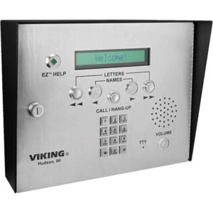
A lot of apartment buildings have callboxes that will dial a tenant and allow the tenant to open the door by pressing a key sequence. I have had to use this to call myself before when I left my keys upstairs, or that time I lost my keys for a week (but thats another story). So what happens if you don’t have your phone or your keys? Or what about when you have guests that arrive early and you’re still in the shower, getting ready or can’t get to your phone in time?

In this example, the callbox dials Tropo instead of your phone, uses the built-in IVR to ask for a password. If the password is correct, it dials the dtmf digits to open the door and sends a text message to your phone alerting you of company.

var
result = ask(“The password is?”, {
choices: “sausages”
});
if(result.value == “sausages”){
say(“that is correct”);
say(“https://evolution.voxeo.com/library/audio/prompts/dtmf/Dtmf-9.wav”);
message(“A Guest has Arrived”, {
to:”+19192223323″,
network:”SMS”
});
}
else{
say(“there is a nice bench outside for you to sleep on”);
}

  1. NAT Exemption – don’t ever nat this
  2. Static Policy NAT – nat to something when this goes to that
  3. Static NAT – nat this to that
  4. Dynamic Policy NAT/PAT – nat to something when these go to that
  5. Identity NAT – don’t nat this when i’m talking
  6. Dynamic NAT – nat all these to this
  7. Dynamic PAT –  nat all these ports to this


First we’ll discuss a basic ipsec tunnel between two ISRs:

RTR-A
Define IKE Phase 1 Policy (ISAKMP)
crytpo isakmp policy 10
encryption aes 256
authentication pre-share
hash sha
group 2

Define pre-shared key
crypto isakmp key pr3sh4r3dk3y address 22.2.1.1 no-xauth

Define IKE Phase 2 Policy (IPSEC)
crypto ipsec transform-set aes-sha esp-aes 256 esp-sha-hmac

Create ACL to match interesting traffic
access-list 150 permit ip host 192.168.1.1 host 192.168.2.1

Create Crypto Map
crypto map vpn-a-to-b 10 ipsec-isakmp
set peer 22.2.1.1
set transform-set aes-sha
match address 150

Apply Crypto Map to Interface
interface Gi0/0
crypto map vpn-a-to-b

Create a route
ip route 192.168.2.1 255.255.255.255 Gi0/0

RTR-B
Define IKE Phase 1 Policy (ISAKMP)
crytpo isakmp policy 10
encryption aes 256
authentication pre-share
hash sha
group 2

Define pre-shared key
crypto isakmp key pr3sh4r3dk3y address 22.1.1.1 no-xauth

Define IKE Phase 2 Policy (IPSEC)
crypto ipsec transform-set aes-sha esp-aes 256 esp-sha-hmac

Create ACL to match interesting traffic
access-list 150 permit ip host 192.168.2.1 host 192.168.1.1

Create Crypto Map
crypto map vpn-b-to-a 10 ipsec-isakmp
set peer 192.168.1.1
set transform-set aes-sha
match address 150

Apply Crypto Map to Interface
interface Gi0/0
crypto map vpn-b-to-a

Create a route
ip route 192.168.1.1 255.255.255.255 Gi0/0

Now the more likely scenario –

two hosts need to talk to the same company and the ips overlap

We’ll use the same instructions, but making some adjustments to RTR-B

Create ACL to match interesting traffic (using natted address this time)
access-list 150 permit ip host 192.168.11.1 host 192.168.2.1

Create route-map
route-map B-to-C permit 10
match ip address B-to-C-ACL

Create ACL to match traffic in the scenario
ip access-list extended B-to-C-ACL
permit ip host 192.168.1.1 host 192.168.2.1

Create NAT statement and apply to interfaces
ip nat inside source static 192.168.1.1 192.168.11.1 route-map B-to-C-ACL extendable

int Gi0/1
description inside
ip nat inside

int Gi0/0
description outside
ip nat outside

 This can be done a little simpler with an ASA using a static policy nat

access-list policy-nat extended permit ip host 192.168.1.1 host 192.168.2.1
static (inside,outside) 192.168.11.1  access-list policy-nat

It surprises me how many times people invest the money in having a redundant edge, but fail to do the simple things: plug into different power sources and have their switch be a single point of failure. With this configuration, you could lose a power source, a firewall, a switch in the stack, and 75% of your cables and still function!

Configure Switch Stack:

vlan 10
name LAN

vlan 777
name ISP1

interface Port-channel1
description Primary ASA
switchport trunk allowed vlan 10,777
switchport mode trunk
!
interface Port-channel2
description Secondary ASA
switchport trunk allowed vlan 10,777
switchport mode trunk
!
interface GigabitEthernet1/0/47
description Primary ASA
switchport trunk allowed vlan 10,777
switchport mode trunk
channel-group 1 mode active
!
interface GigabitEthernet1/0/48
description Secondary ASA
switchport trunk allowed vlan 10,777
switchport mode trunk
channel-group 2 mode active
!
interface GigabitEthernet2/0/47
description Primary ASA
switchport trunk allowed vlan 10,777
switchport mode trunk
channel-group 1 mode active
!
interface GigabitEthernet2/0/48
description Secondary ASA
switchport trunk allowed vlan 10,777
switchport mode trunk
channel-group 2 mode active
!

Configuration Primary ASA:

interface GigabitEthernet0/0
channel-group 1 mode active
no nameif
no security-level
no ip address
!
interface GigabitEthernet0/1
channel-group 1 mode active
no nameif
no security-level
no ip address
!
interface Port-channel1
no nameif
no security-level
no ip address
!
interface Port-channel1.10
vlan 10
nameif LAN
security-level 100
ip address 172.17.10.10 255.255.255.0 standby 172.17.10.11
!
interface Port-channel1.777
vlan 777
nameif ISP1
security-level 0
ip address 24.222.111.25 255.255.255.240

interface GigabitEthernet0/5
description LAN/STATE Failover Interface

failover
failover lan unit primary
failover lan interface failover GigabitEthernet0/5
failover link failover GigabitEthernet0/5
failover interface ip failover 10.255.255.1 255.255.255.252 standby 10.255.255.2
monitor-interface LAN

Configure Secondary ASA:

failover
failover lan unit secondary
failover lan interface failover GigabitEthernet0/5
failover link failover GigabitEthernet0/5
failover interface ip failover 10.255.255.1 255.255.255.252 standby 10.255.255.2
monitor-interface LAN

Recently when replacing an ASA5510 with a new ASA5545X, I noticed the nat was not working for a couple public ips. I used the following command to capture any packets attempting to hit that ip. The problem ended up being an arp cache issue that had to involve the provider. Something to keep in mind with fiber services – the device on site is not a layer 3 device, it only converts fiber to copper. The device that needed to be flushed was at the provider end, miles away.

cap o type raw-data int OUTSIDE match ip any host 60.33.70.69

show cap

I recently configured one of the new software IPS modules in an ASA X series firewall and after the initial setup, I could not access the IPS module from ASDM or from IME (IPS Management Express). I found that there are two requirements before the IPS will talk.

1. If the IPS ip address is on a different subnet than the management network (192.168.1.0 by default), you’ll need to issue “no nameif” on the Management0/0 interface

2. Even if you decide not to use the Management0/0 for ASA management, it must be in an UP and UP state, so you’ll need to connect it to your switch.

interface Vlan99
description guest
ip address 10.99.99.1 255.255.255.0
ip access-group Public-Out in

ip access-list extended Public-Out
permit udp any any eq bootps
deny   ip 10.99.99.0 0.0.0.255 192.168.0.0 0.0.255.255
deny   ip 10.99.99.0 0.0.0.255 172.16.0.0 0.0.15.255
deny    ip 10.99.99.0 0.0.0.255 10.0.0.0 0.0.0.255
permit ip 10.99.99.0 0.0.0.255 any

New York:

crypto isakmp key pr3sh4r3dk3y! address 2.2.2.2 no-xauth

crypto ipsec transform-set GRE esp-des esp-md5-hmac
mode transport
!
crypto ipsec profile GRE_Tunnel
set transform-set GRE

interface Tunnel1
description GRE to Miami
ip address 192.168.1.1 255.255.255.0
delay 100
tunnel path-mtu-discovery
tunnel source GigabitEthernet0/1
tunnel destination 2.2.2.2
tunnel protection ipsec profile GRE_Tunnel

interface GigabitEthernet0/1
ip address 1.1.1.1 255.255.255.252

Miami:

crypto isakmp key pr3sh4r3dk3y! address 1.1.1.1 no-xauth

crypto ipsec transform-set GRE esp-des esp-md5-hmac
mode transport
!
crypto ipsec profile GRE_Tunnel
set transform-set GRE

interface GigabitEthernet0/1
ip address 2.2.2.2 255.255.255.252

interface Tunnel1
description GRE to New York
ip address 192.168.1.2 255.255.255.0
delay 100
tunnel path-mtu-discovery
tunnel source GigabitEthernet0/1
tunnel destination 1.1.1.1
tunnel protection ipsec profile GRE_Tunnel

sla monitor 10
type echo protocol ipIcmpEcho 8.8.8.8 interface outside
num-packets 3
timeout 1000
frequency 3
sla monitor schedule 10 life forever start-time now
track 1 rtr 10 reachability

route outside 0.0.0.0 0.0.0.0 24.176.24.1 1 track 1
route backupisp 0.0.0.0 0.0.0.0 70.69.131.1 254

This example will redistribute vpn traffic into your eigrp network.

1. Turn on reverse route for your crypto maps

crypto dynamic-map Outside_dyn_map 20 set reverse-route <– for a remote access VPN
crypto map Outside_map 1 set reverse-route  <– for a L2L tunnel

2. Make route map and define traffic

access-list VPN-Redistribute standard permit 10.222.222.0 255.255.255.128  <– VPN traffic
route-map Redistribute permit 5
match ip address VPN-Redistribute

3. Define eigrp process, including your inside network

router eigrp 10
network 10.254.254.0 255.255.255.224
redistribute static route-map Redistribute